Funktionsprinzip der durchflussgesteuerten Servoventile
 4-Weg Servoventile
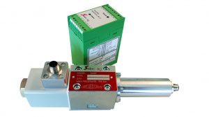
Das Selec Servo Ventil ist einfach in der Funktion, robust in der Konstruktion und zuverlässig bezüglich einer optimalen Systemkontrolle und einer langen, problemlosen Funktion.
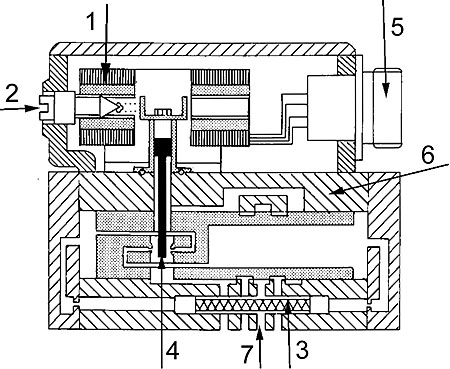
1. Double air gap low DC current dry torque motor (130 ma Standard, andere erhältlich)
- Extremely stiff and well dampened to achieve the best dynamic properties.
- Large encapsulated coils provide a very stable and rugged magnetic system.
- Magnetsystem ist nicht in Kontakt mit der Flüssigkeit.
- Kann mit Flüssigkeiten mit hohem Wasseranteil eingesetzt werden.
- Keine mechanische Berührung zwischen Magnetsystem und Kolben.
2. Externe 0-Punkt-Justierschraube
- Einfacher Zugang für die Feineinstellung des 0-Punktes.
3. Integrierter 55 micron-Filter
- Schützt Blenden und Düsen vor Partikeln und daraus resultierenden Präzisionsverlusten des Servo Ventils.
- Einfach zugänglich
4. Kolben mit integriertem hydraulischem Feedback
- Feedback of the second stage (power) spool is provided by the unique patented design which throttles the nozzles mounted within the spool. This design eliminates the need for a cantilever feedback spring and long control passages in the second stage spool control areas. The short symmetrical pilot lines improve frequency response while the elimination of the feedback spring results in high reliability.
- The control edges of the power spool and cylinder are hardened, ground and lapped.
5. Robuste elektrische Verbindung
- A simple easy to plug-in electrical connection using four pin MS receptacle and mating connector plug with cable clamp and boot is standard.
6. Robuster Stahlkörper
- Korrosionsfest (Kompatibel mit Flüssigkeiten mit hohem Wasseranteil)
7. Standard Cetop-Norm für Anschlussbilder
- Mounts on standard sub-plates or bar manifolds
- Ersetzt Proportional Ventile mit ungenügender Performance.
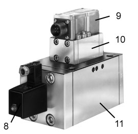
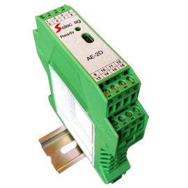
8. Selec Servo Ventile können für die beste Perfomance mit der Selec Verstärkerelektronik AE-1 / AE-2 betrieben werden, aber auch mit Verstärkerelektroniken anderer Hersteller.
- Rail-mounted amplifier for servo or proportional solenoid controlled valves.
- Built-in flow, pressure, pressure and horsepower limiting, and load sense program configurations.
- Closed-loop control for a single valve.
- Built-in password protected parameter and program setup valves
LVDT
- Ein „linear variable differential transformer“ (L.V.D.T.) wird bei den Ventilen S120, S120E und S300 für die Kolbenpositionsüberwachung eingesetzt.
9. Magnetsystem / Hebel (erste Stufe)
10. Zweite Stufe
- Der Kolben der zweiten Stufe ist Pilot für dreistufige Servo Ventile.
11. Dritte Stufe
- Hat einen Linear Variable Differential Transformer (L.V.D.T.) für das feedback.
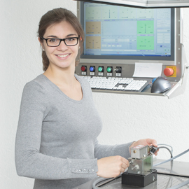
Selec’s grosse Erfahrung auf vielen Anwendungen
- Selec ist seit 1969 elektrohydraulischer Hersteller und gerne bereit Ihnen zu helfen.
Performance assurance is standard with every Selec component
The total dedication to performance is based upon experience gained since 1969 in matching fluid power equipment to a tremendous variety of machines and applications.
Selec’s Performance Assurance is made possible because of experience gained over the years in supplying machinery builders and users with unique solutions to thousands of unusual fluid power problems. Historically, Selec has concentrated its energies on hydraulics and electrohydraulic equipment and systems.
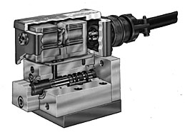
Principle of operation
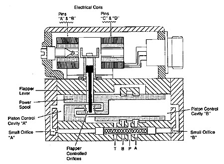 Fig. A
Zwei stufige Servo Ventile
Die erste Stufe von einem zwei stufigen Servo Ventil, Fig. A, ist die Strom- (mA) betriebene Stufe.
Elektrischer Strom in den Spulen erzeugt ein magnetisches Feld, welches den Hebel (Flapper lever) proportional zum Strom auslenkt.
Die Bewegung des Hebels unterbricht das Druckgleichgewicht, zwischen Kolben und Hebel. Der Kolben verschiebt sich in der Richtung des Hebels, bis das Druckgleichgewicht wieder hergestellt ist.
Obwohl die Kraft des Hebels sehr klein ist, wird durch die hydraulische Kraftverstärkung an den Düsen (Flapper controlled orifices) und beaufschlagte Kolbenfläche (piston control cavity „A“ / „B“) genügend Kraft erzeugt um den Kolben genau zu positionieren.
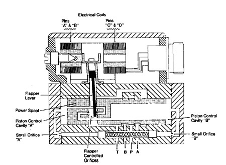 Fig. B
Wenn ein positiver Strom von pin „A“ und „C“ zu pin „B“ und „D“ fliesst, bewegt sich der Hebel nach rechts (Fig. B).
Diese Bewegung des Hebels erhöht den Druck an der Düse auf der rechten Seite und verringert den Druck an der Düse auf der linken Seite.
Das Resultat ist ein Druckanstieg in der Kolbenkammer links (piston control cavity „A“) die mit Oel des Druckanschlusses über die Blende (small orifice „A“) versorgt wird.
Wenn ein positiver Strom von „A“ und „C“ zu pin „B“ und „D“ fliesst, bewegt sich der Hebel nach rechts (Fig. B).
Diese Bewegung des Hebels erhöht den Druck an der Düse auf der rechten Seite und verringert den Druck an der Düse auf der linken Seite.
Das Resultat ist ein Druckanstieg in der Kolbenkammer links (piston control cavity „A“) die mit Oel des Druckanschlusses über die Blende (small orifice „A“).
Gleichzeitig, nimmt der Druck in der rechten Kolbenkammer ab weil sich die Tankleitung „T“ (drain) öffnet.
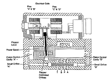 Fig. C
The pressure imbalance moves the power spool to the right until the flapper controlled nozzle gaps are equal and pressure in cavities „A“ and „B“ are once again equal as shown in figure „C“. The repositioning of the power spool will result in pressure port “P” being connected to control port „B“ and control port „A“ connected to tank or drain port „T“.
By reversing the DC current direction from the above example, the flapper and main spool will move to the left and port „P“ will be connected to control port „A“ and control port „B“ connected to tank „T“ (drain).
Three-Stage Servo Valves
In the three-stage servo valve, the pilot valve is a standard VSC4-R03 two stage servo valve. This pilot valve directs fluid flow to position the third stage power spool. A Linear Variable Differential Transformer (LVDT) attached to the third stage generates an electrical feedback signal proportional to spool movement. The electronic package controlling the valve must supply the excitation for the LVDT as well as the signal conditioning circuitry for summing the feedback signal with the command. The standard Selec Amplifier Module provides all these functions.
When an error exists between the command signal and the conditioned LVDT feedback signal, the amplifier produces an output current to the two-stage pilot valve. This pilot valve in turn ports fluids to and from piston cavity areas „C“ and „D“ to shift the third stage spool. As the third stage spool moves, the LVDT feedback signal will change accordingly to cancel the command signal.
When the sum of the command voltage and the feedback volt is zero, the current output of the amplifier will also be zero. The result is the centering of the pilot valve. The pressure in piston control cavity „C“ and „D“ will be equal and the third stage spool will be at a new offset stable position.
If the error signal between the command and feedback signal was opposite in polarity, the valve would shift in the opposite direction. The polarity and amplitude of a command voltage determines the direction and magnitude of spool offset and flow.